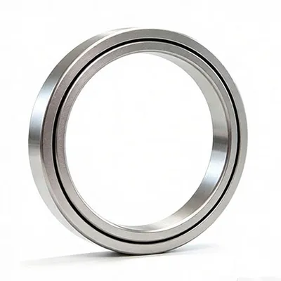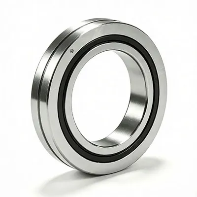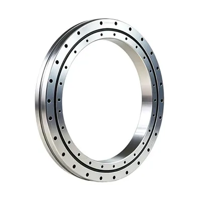
Cross roller bearings are widely used in applications that require high rotational accuracy, rigidity, compact dimensions, and reliable motion control. However, the performance of a cross roller bearing depends on more than the bearing itself. The quality of the installation can directly affect rotational torque, running accuracy, preload, noise, service life, and the ability of the bearing to carry its designed load.
For engineers, maintenance teams, and equipment manufacturers, understanding the correct cross roller bearing installation procedure is therefore essential. A bearing that has been manufactured to tight tolerances can still develop excessive friction, uneven rotation, or premature wear if the mounting surfaces are inaccurate, the bearing is installed with excessive force, or the fixing bolts are tightened unevenly.
This guide explains the key steps involved in installing a cross roller bearing, from preparation and mounting surface inspection to fastening, lubrication, preload verification, and final testing.
Why Proper Cross Roller Bearing Installation Matters
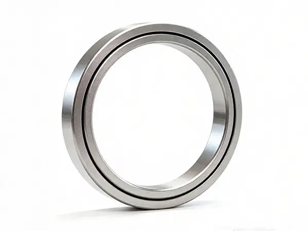
A cross roller bearing uses cylindrical rollers arranged alternately at 90-degree orientations. This arrangement allows the bearing to support radial loads, axial loads, and moment loads within a compact structure. The line contact between the rollers and raceways also contributes to high rigidity and positioning accuracy.
Because the bearing is designed for precision applications, the surrounding structure becomes an important part of the complete bearing system. If the housing, shaft, mounting flange, or base has insufficient rigidity or poor geometric accuracy, the bearing may not distribute the load evenly. Manufacturer guidance also emphasizes that inaccurate or insufficiently rigid mounting components can concentrate the bearing load in one area and reduce performance.
Proper installation helps the bearing achieve:
- Stable rotational performance
- Low and consistent friction
- High running accuracy
- Appropriate preload or clearance
- Better load distribution
- Reduced vibration and operating noise
- Longer service life
For precision machinery, installation accuracy should therefore be considered part of the bearing selection and system design process rather than a final assembly task.
Step 1: Inspect the Bearing and Mounting Components
Before installation, the technician should inspect the cross roller bearing, housing, shaft, mounting flange, fixing bolts, and other related components.
The technician should verify that the bearing model and dimensions correspond to the machine design. The technician should also check the bearing for visible damage caused by transportation or improper handling.
The mounting surfaces should remain clean and free from dust, metal chips, grease contamination, burrs, and other foreign particles. Even small particles between the bearing and mounting surface can affect seating accuracy and create localized stress.
The installer should also inspect the dimensional accuracy of the housing and shaft. The required tolerances, fit, flatness, perpendicularity, parallelism, and other geometric requirements should follow the bearing manufacturer's drawings and technical specifications.
For high-precision applications, the mounting surface deserves particular attention because the bearing can reproduce errors from the surrounding structure during operation. Precision bearing installation guidance from Parker and other manufacturers similarly identifies mounting-surface accuracy as a critical factor in achieving repeatable motion.
Step 2: Clean the Mounting Surface Carefully
The installer should clean the housing and shaft before placing the bearing into position.
A clean lint-free cloth can remove surface contamination, while an appropriate cleaning agent can help remove oil, debris, or residual machining particles. After cleaning, the technician should ensure that the surface is completely free from burrs and raised areas.
The installer should never assume that a newly machined housing is ready for assembly. Machining operations can leave small burrs or particles around bolt holes, shoulders, and seating surfaces.
The technician should also keep the bearing itself protected from contamination during the entire installation process. Cutting chips, coolant, dust, and other foreign materials can enter the rolling path and damage the raceways or rolling elements.
Step 3: Keep the Bearing in Its Original Assembly Condition
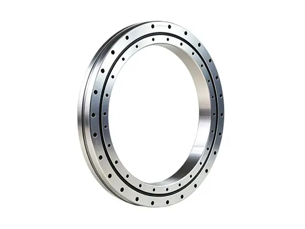
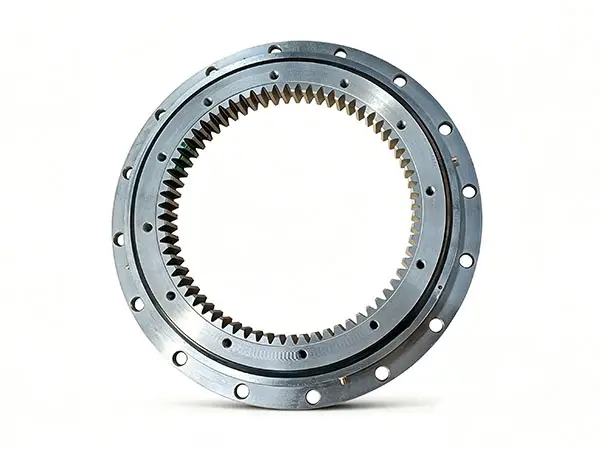
Many cross roller bearings use a split inner ring or outer ring that is secured with special rivets, bolts, or nuts. The installer should normally install the bearing in the condition in which it was supplied.
The technician should not casually separate the split ring or remove internal spacers and rolling elements. Incorrect reassembly can change the relationship between the rollers, spacers, and raceways and can significantly affect rotational performance.
The installer should also avoid applying force directly to securing rivets, connecting bolts, or other retaining components during installation or removal. THK specifically warns against disassembling cross roller rings and against applying installation forces to securing rivets or bolts.
If the joint of a split ring is slightly misaligned, the technician should follow the manufacturer's specified correction procedure rather than forcing the ring into position.
Step 4: Align the Bearing Before Pressing It Into Position
The installer should align the bearing carefully with the housing or shaft before applying mounting force.
Cross roller bearings can have relatively thin sections, which means the bearing can tilt if the installer pushes one side too deeply before the opposite side has entered the mounting position. Uneven insertion can introduce deformation and affect the running condition.
The technician should therefore keep the bearing level and apply force progressively and evenly around the appropriate ring. If a manufacturer permits light tapping during installation, the technician should use a suitable non-metallic tool and distribute the force around the circumference.
The installer should never strike the free or non-fixed ring simply because it is easier to access. The correct ring must receive the installation force according to the specific mounting arrangement. For example, THK advises that when the inner ring is fixed, the inner ring should receive the insertion force; when the outer ring is fixed, the outer ring should receive the force.
For high-precision assemblies, using a controlled pressing method is preferable to impact installation whenever the equipment design allows it.
Step 5: Install the Mounting Flange or Clamping Ring
After the bearing has been correctly seated, the installer can position the mounting flange, clamping ring, or presser flange.
The flange should make proper contact with the bearing ring without creating excessive deformation. The dimensional tolerances of the surrounding components should allow the flange to hold the bearing securely from the side.
The technician should initially insert the fixing bolts by hand. This step allows the installer to identify misaligned holes before significant clamping force is applied.
The installer should then tighten the bolts gradually rather than tightening one bolt completely before moving to the next one. A diagonal or crosswise tightening sequence helps distribute the clamping force more evenly.
For example, a practical sequence can follow this general pattern:
Initial positioning → hand-tightening → diagonal tightening → intermediate torque → final specified torque
The exact bolt size and tightening torque should always come from the bearing manufacturer's assembly drawing or technical documentation. The installer should not substitute a generic torque value simply because the bolt appears similar.
HIWIN installation documentation likewise recommends inserting the mounting bolts first and tightening them progressively in a diagonally opposite sequence instead of tightening the bolts simultaneously to full torque.
Step 6: Check Preload and Rotational Resistance
Preload is one of the most important factors in a precision cross roller bearing system.
The correct preload can reduce internal play and improve rigidity and positioning stability. However, excessive preload can increase rotational resistance, heat generation, and contact stress. Schaeffler notes that bearing rotational resistance is affected by factors such as preload, rolling resistance, seals, grease, and fitting errors, while excessive preload at higher speeds can contribute to significant heat generation.
The installer should therefore avoid trying to achieve "zero clearance" by simply tightening components as much as possible.
If the bearing design includes an adjustable preload mechanism, the technician should follow the manufacturer's adjustment procedure and use the specified measurement method. Depending on the bearing type, the technician may monitor displacement, running resistance, torque, or another defined parameter during adjustment.
A precision assembly should produce smooth and consistent movement throughout the operating range. Any sudden increase in resistance may indicate incorrect preload, mounting deformation, contamination, misalignment, or another assembly problem.
Step 7: Lubricate the Cross Roller Bearing Correctly
Lubrication directly affects friction, temperature, wear, and bearing life.
Many cross roller bearings are supplied with factory-applied grease and can be used immediately when installed according to the manufacturer's instructions. However, the lubrication requirement varies according to bearing design, operating speed, load, temperature, environment, and duty cycle.
The installer should use a lubricant that is compatible with the bearing and application. The technician should not mix different greases simply because both products appear to have similar base properties. Different additives or thickener systems can interact negatively after mixing.
The technician should also avoid overfilling the bearing. Excessive grease can temporarily increase rotational torque and may increase operating temperature.
For open cross roller bearings, the lubrication interval should be determined from actual operating conditions rather than treated as a universal number. Some manufacturer recommendations provide several-month intervals as a starting point, but the final maintenance schedule should consider speed, load, temperature, contamination, and operating frequency.
Step 8: Rotate and Test the Bearing After Installation
The installer should not consider the installation complete immediately after tightening the final bolt.
The technician should slowly rotate or move the bearing through its intended operating range. The movement should remain smooth and should not produce unusual grinding, sticking, abnormal noise, or sudden changes in resistance.
The technician should also check whether the bearing generates unusual heat during initial operation. A temporary increase in temperature or torque can occur while grease distributes throughout the bearing, but continued abnormal heating can indicate excessive preload, incorrect lubrication, excessive load, uneven mounting, or inaccurate adjacent components.
For precision machinery, the technician should use appropriate measuring equipment, such as a dial indicator, to verify running accuracy. Schaeffler recommends checking running accuracy with a dial gauge and investigating deviations that may result from adjacent construction errors or unevenly tightened clamping components.
Common Cross Roller Bearing Installation Mistakes
Several installation mistakes occur repeatedly in precision machinery assembly.
- The technician installs the bearing without checking the housing
An inaccurate housing can prevent the bearing from seating correctly. The technician should verify the housing dimensions and geometric accuracy before assembly.
- The installer strikes the wrong bearing ring
The wrong installation force path can damage the bearing or create raceway deformation. The installer should always determine which ring is fixed before applying insertion force.
- The technician tightens one bolt completely at once
Uneven clamping can distort the bearing or create uneven internal loading. The technician should tighten the bolts gradually in the specified sequence.
- The installer uses excessive preload
More preload does not automatically mean more precision. Excessive preload can increase friction, temperature, and wear.
- The technician ignores contamination
Small particles can enter the rolling path and create abnormal noise, wear, or premature failure. The assembly environment should remain as clean as reasonably possible.
- The installer mixes different lubricants
Different grease formulations may not be compatible. The technician should follow the bearing manufacturer's lubricant recommendations.
- The technician skips the final accuracy check
A bearing may rotate after installation while still failing to meet the required running accuracy. Precision applications should include an appropriate measurement and verification procedure.
Cross Roller Bearing Installation Checklist
Before commissioning the equipment, the maintenance or assembly team can use the following checklist:
- Confirm the bearing model and dimensions.
- Inspect the bearing for transportation damage.
- Check the housing, shaft, and mounting flange dimensions.
- Remove burrs and foreign particles from mounting surfaces.
- Keep the bearing in its original assembled condition.
- Align the bearing carefully before insertion.
- Apply installation force only to the appropriate fixed ring.
- Install the flange or clamping ring without excessive compression.
- Insert all fixing bolts before final tightening.
- Tighten bolts progressively and diagonally.
- Adjust preload according to the manufacturer's specification.
- Apply compatible lubricant at the correct quantity.
- Rotate or stroke the bearing manually after assembly.
- Check for abnormal noise, resistance, vibration, or temperature.
- Measure running accuracy when the application requires precision verification.
- Record the installation results for future maintenance reference.
How to Improve Cross Roller Bearing Installation Reliability
A reliable installation process starts before the bearing reaches the assembly station. The equipment manufacturer should define the required mounting accuracy, housing structure, fixing method, preload condition, lubricant, and inspection method during the design stage.
The assembly team should also use controlled tools rather than relying entirely on manual judgment. A calibrated torque wrench can improve bolt-tightening consistency, while a dial indicator can help identify running accuracy deviations.
When a bearing shows abnormal resistance after installation, the technician should avoid forcing the mechanism to run. The technician should instead inspect the mounting surfaces, bolt tightening sequence, preload, lubrication condition, bearing alignment, and adjacent components.
This approach can prevent a small installation error from becoming a more expensive equipment failure.
Final Thoughts
Cross roller bearing installation is a precision assembly process rather than a simple press-fitting operation.The bearing, housing, shaft, mounting flange, fasteners, lubricant, and preload condition all work together to determine the final performance of the system.
A successful installation requires clean mounting surfaces, accurate alignment, controlled installation force, even fastening, correct lubrication, appropriate preload, and post-installation testing. When these factors are properly controlled, the cross roller bearing can deliver the high rigidity, compact structure, smooth motion, and positioning accuracy expected from precision bearing applications.
For equipment manufacturers and engineers who need to select or customize a cross roller bearing, the installation environment should be discussed with the bearing supplier before finalizing the design. Bearing dimensions, internal clearance or preload, mounting configuration, lubrication, operating speed, load conditions, and required accuracy should be evaluated together. This approach helps ensure that the selected bearing is not only suitable on paper but also practical to install and reliable in the finished machine.
Important note:The exact installation method, interference or clearance requirements, bolt torque, preload, lubrication quantity, and inspection tolerances vary between cross roller bearing designs and manufacturers. The manufacturer's product drawing and installation manual should always take priority over general installation practices.